Percentage impedance of transformer pdf
Effective percentage impedance Short circuit stresses Electrical connection Equipment in LV may be under high potential Impulse problem (over-voltage) is more severe Voltage regulation. PROBLEM: Short circuit stresses Black and white FEA program magnetic field plots Auto-transformer with taps in main body of series winding Auto-transformer with taps in a separate tap winding. ANALYSIS
A quarter-wave impedance transformer, often written as λ/4 impedance transformer, is a transmission line or waveguide used in electrical engineering of length one-quarter wavelength (λ), terminated with some known impedance.
Purpose. There are several reasons for using a per-unit system: Similar apparatus (generators, transformers, lines) will have similar per-unit impedances and losses expressed on their own rating, regardless of their absolute size.
consider only the transformer impedance. The HV supply usually has a far greater capacity and can supply a transformer shorted on its output with little drop (5% is a typical figure) in voltage. Neglecting the impedance of the HV supply makes the calculation very simple if the transformer impedance is known. Typical values are listed in Table 1. The calculation for maximum fault current is ; I
Special Note: In 3 phase transformer systems, divide V LL by √3 (square root of 3) Also, in the ‘per unit’ system, the short circuit current multiple is the inverse of % impedance.
Two types of voltage transformer are used for protective-relaying purposes, as follows: (1) practically in parallel resonance were it not for the presence of the burden impedance. Fig. 3. Schematic diagram of a Class A potential device. Fig. 4 Equivalent circuit of a Class A potential device. VOLTAGE TRANSFORMERS 121 The gross input in watts from a power circuit to a capacitance potential
Impedance Transformer Electrical Impedance Scribd

Per-unit system Wikipedia
www.learnabout-electronics.org Impedance AC THEORY MODULE 07.PDF 2 E. COATES 2007 -2010
Full text of “IS 2026-1: Power transformers, For transformers having a tapped winding with tapping range exceeding ±5 percent, impedance values are also to be given for the two extreme tappings. On such transformers these three values of impedance shall also be measured during the short-circuit test {see 10.4). When impedance values are given for several tappings, and particularly when
In electronics, impedance matching is the practice of designing the input impedance of an electrical load or the output impedance of its corresponding signal source to maximize the power transfer or minimize signal reflection from the load.
magnetizing impedance is assumed to be much larger than the secondary resistance and secondary leakage reactance. This is typically a good assumption for practical transformer
An impedance transformer of even-order n with r open- circuit stubs and (n – r) unit elements, as shown in Fig. 2, has r transmission zeros at p + co, corresponding to the
(a) Transmission line model of 4:1 Guanella transformer. (b) Cross section of the five-layer line, where layers 1, 3, and 5 are 100 m tall and layers 2 and 4 are 50 m tall.
transformer is usually relatively small so that its impedance will typically limit the differential current to a level below the minimum pickup of the percentage restraint characteristic.
transformer does not meet the requirement of 1% impedance for 10HP drive. Evaluating short circuit impedance Power source impedance is also and easy way to evaluate available short circuit rating.
How to calculate transformer impedance? Monday, September 21, 2015. There are three ways to explain Percentage Impedance: 1) It is the % voltage drop in secondary no load voltage when a rated full load zero power factor lagging current is taken from secondary. It is the price one has to pay for transferring the current from primary to secondary side. Higher the % impedance, higher the
1 August 2007 2006 by Fabian Kung Wai Lee 1 3A. Impedance Transformation and Impedance Matching The information in this work has been obtained from sources believed to be reliable.
6/06/2011 · The normal method of expressing transformer impedance is as a percentage voltage drop in the transformer at full-load current and this reflects the way in which it is seen by
of a few percent of the nominal voltage and this 5% voltage is applied across primary. The core losses are very small because applied voltage is only a few percentage of the nominal voltage and hence can be neglected. Thus the wattmeter reading measures only the full load copper loss. The connection diagram for short circuit test on transformer is shown in the figure. A voltmeter, wattmeter
Zin is the input impedance. It is the steady state impedance or “resistance” It is the steady state impedance or “resistance” of the source inductor coil when it is coupled with the load coil in the transformer.
Transformer Design: Short-circuit impedance •Current carrying conductors in a magnetic field experience force in accordance with Fleming’s left hand rule. •Axial flux produces radial force and radial flux produces axial force •Conductors are attracted to each other when currents are in same direction •Conductors are pushed away from each other when currents are in opposite direction
The transformer impedance is a physical constant determined by the construction of the transformer and the material used. It basically does not change. The percent impedance (or impedance voltage) is expressed as percentage (or per unit) referenced to some base MVA. For an ANSI-rated transformer, the %Z is expressed in terms of the lowest transformer kVA rating (generally, but not always), the
transformers shall be double copper wound, three phase, oil immersed with ONAN cooling and fitted with on load tap changers for 8.00 MVA Transformer only. The ratings required are 3.15 MVA, 5.0 MVA and 8.0 MVA. The transformer shall conform in all respects to highest standards of engineering, design, workmanship, this specification and the latest revisions of relevant standards at the time of

The percentage impedance of a transformer is the volt drop on full load due to the winding resistance and leakage reactance expressed as a percentage of the rated voltage. It is also the percentage of the normal terminal voltage required to circulate full-load current under short
Percentage Impedance (Z%) More on Impedance. The Impedance of a Transformer is marked on most rating plates. Definition The percentage impedance of a Transformer is the volt drop on full load due to the winding resistance and leakage reactance expressed as a percentage of the rated voltage.
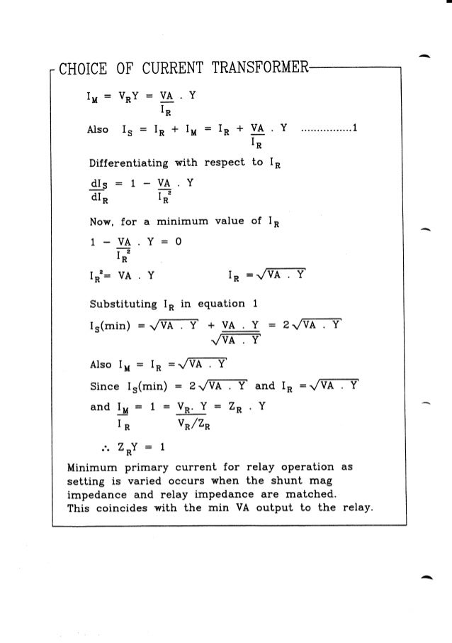
Let the primary of the transformer winding has 1000 turns while secondary has 500 turns. If the primary CT ratio is 100:5, find the CT ratio required in the secondary side to establish circulatory current scheme.
The impedance of a transformer is defined as the percentage of the drop in voltage to the at full load to the rated voltage of the transformer. This drop in voltage is …
TECHNICAL NEWS nhp.com.au
8/07/2010 · The percentage impedance of a transformer is the volt drop on full load due to the winding resistance and leakage reactance expressed as a percentage of the rated voltage – so measure the voltages on an off load It is also the percentage of the normal terminal voltage required to circulate full-load current under short circuit conditions – again measure the voltage you need to get FLC
The percentage impedance of a transformer is the voltage drop under full load current due to the winding resistance and leakage reactance expressed as a percentage of the rated voltage. The impedance is measured by means of a short circuit test.
This is a negative factor. On the other hand, if percentage impedance of a transformer is less, voltage drop on transformer winding will be less which will facilitate better voltage regulation. This is a positive factor. Therefore, percentage impedance of transformer has to be precisely selected to maintain a proper balance between fault level and voltage regulation. PERMITTED TOLERANCE IN Z
Unless the transformer is quite small, equivalent resistance is negligible and percent reactance may be substituted for percent impedance in the above equation (iv). Another method of designating the resistances and reactances is by the per unit values.
The percent impedance (or impedance voltage) is expressed as percentage (or per unit) referenced to some base MVA. For an ANSI-rated transformer, the %Z is expressed in terms of the lowest transformer kVA rating (generally, but not always), the self-cooled rating. The base MVA of the percent impedance should be stated on the nameplate. For IEC-rated transformers, I believe the %Z is … – abundance by steven kotler and peter h diamandis pdf impedance figure. Percent impedance describes the percent of nominal voltage (impedance voltage) required to flow rated current through a shorted secondary. Percent regulation will approach this figure under reactive loads. A higher impedance, or %Z, will result in a higher output voltage variance and therefore, potentially reducing the medical equipment’s ability to produce quality images
PDF A theoretical investigation of the use of a coupled line section as an impedance transformer is presented. We show how to properly select the terminations of the coupled line structures for
The percent of impedance value is 793.5 / 13800 = 0.0575. Therefore; % Z = 0.0575 x 100 = 5.75% This shows that if there was a 3-Phase Bolted fault on the secondary of the transformer then the maximum fault current that could flow through the transformer would be the ratio of 100 / 5.75 times the FLA of the transformer, or 17.39 x the FLA = 20,903A . 3 Based on the infinite source method at
impedance of the transformer. Example: For a 480 Volt rated primary, if 9.6 volts causes secondary full load current to flow through the shorted secondary, the transformer impedance …
ELG4125: Lecture 2 Power Transformers The Ideal Transformer The Real Transformer Equivalent Circuits for Practical Transformers The Per-Unit System Three-Phase Transformers Autotransformers . Transformers in Power Systems • Typically in power systems, voltages get transformed approximately five times between generation and delivery to the users. • Generation in power systems, primarily by
Understand the concept of a reflected load in a transformer, and its application in impedance matching. Study the application of transformers in electrical energy distribution and power supplies.
Impedance – Download as PDF File (.pdf), Text File (.txt) or read online. The percentage impedance of a transformer is the volt drop on full load due to the winding resistance and leakage reactance expressed as a percentage of the rated voltage.
Calculate the percent impedance for a reactor that has a per phase inductance of .001475 Henries that is used on a drive with 16 A of input current flowing at 480 V and at a 60 Hz fundamental frequency.
The percentage impedance of the transformer is calculated as . Z%= (Impedance Voltage/Rated Voltage)*100. Thus a transformer with a primary rating of 110V which requires a voltage of 10V to circulate the rated current in the short-circuited secondary would have an impedance of 9%.
If R 1 and R 2 and X 1 and X 2 are primary and secondary resistance and leakage reactance of transformer respectively, then Z 1 and Z 2 impedance of primary and secondary windings are respectively, The Impedance of transformer plays a vital role during parallel operation of transformer.
The Impact of Mains Impedance on Power Quality By Michael J. Russell, Consulting Electrical Engineer PowerLines, P.O. Box 1164, Waterbury, CT 06721-1164 mrussell@powerlines.com Abstract Mains impedance is a critical parameter to consider when diagnosing load generated power quality problems. High impedance can contribute to voltage sags, low voltage conditions, high frequency …
The percent impedance is the percent voltage required to circulate rated current flow through one transformer winding when another winding is short-circuited at the rated voltage tap at rated frequency. %Z is related to the short circuit capacity of the transformer during short circuit conditions
The percent impedance voltage, as measured on the rated voltage connection, shall be per Table 2. For target impedances, the tolerance on the impedance shall be +/- 7.5%
Transformer Impedance Table Approximate Values of Resistance, Reactance, Impedance and X/R Ratios of 600 Volts or Less, 60 Cycles, 3-Phase, Standard Transformers. (Values in percent on …
“The percentage impedance of a transformer is the volt drop on full load due to the winding resistance and leakage reactance expressed as a percentage of the rated voltage.”
In other words percentage impedance or per unit values of impedance should be identical for all the transformers run in parallel. When connecting single-phase transformers in three-phase banks, proper impedance matching becomes even more critical.
Dry Transformer Percent Impedance Definition
Percentage Impedance (Z%) The impedance of a transformer is marked on most nameplates – but what is it and what does the Z% figure mean? Definition The percentage impedance of a transformer is the volt drop on full load due to the winding resistance and leakage reactance expressed as a percentage of the rated voltage.
Impedance voltage at rated current 5 Impedance voltage 5 Resistance voltage 5 Reactance voltage 5 Sustained short-circuit current 5 Voltage drop 5 Effi ciency 6 Connections and vector groups 6 Noise level 7 Tolerances 7 60 Hz rated frequency 8 60 Hz supply 8 Design for 60 Hz with 10% higher rated power 8 Single-phase transformers 8 Testing 8 Routine tests 8 Type and special tests 9 Acceptance
transformer B which is to be parallel to A must have an impedance between the limits of 3.7% and 4.3%. When paralleling three phase transformers the same precautions must be
Ground fault current for impedance grounded neutral transformer for faults at different % of the winding. Transformer Protection Principles 47 phase shift of the protected transformer. Traditional installations may use delta-connected or wye-connected CTs that externally compensate the measured currents for the phase shift of the protected transformer. GE Multilin accommodates both methods …
Page 1 of 2 IMPEDANCE, SHORT CIRCUIT CURRENTS, AND VOLTAGE DISTORTION General This application note addresses the significance of the output impedance of a transformer to
For example, IEC recommend 4%Z minimum impedance for a 300 kVA transformer. It does not mean however that you could have a 6.5%Z. Yes you can, there will be nobody preventing you to do that but transformer %Z in directly proportional to the transformer cost, size, and weight.
The short-circuit impedance is the transformer’s impedance. Usually between 4% and 6% for distribution transformers and higher than 7% for power transformers, the short-circuit impedance is the percentage of the primary rated voltage that has to be applied at the transformer primary winding when the secondary winding is short-circuited in order to have the rated currents in the primary and
Ideal transformer The relationship between the primary i p (t) and secondary i s (t) currents is () 1 p s it i t a Phasor notation: p s a V V p 1 s a I I • The phase angles …
(PDF) Coupled Transmission Lines as Impedance Transformer

Tx Sizing McGlynn Consultancy
Module 10 Differential Protection of Bus Transformer
CALCULATING PERCENT IMPEDANCE FOR AC LINE REACTOR
Percentage Restrained Differential Percentage of What?


energy.odisha.gov.in
Source Impedance #04 controlledpwr.com
– % Impedance of Power Transformer my.control.com
Percentage of Impedance of Transformers Power Magnetics Inc.

Quarter-wave impedance transformer Wikipedia
Percentage Impedance Transformer Electrical Impedance
Full text of “IS 2026-1 Power transformers Part 1 General”
Impedance Transformer Electrical Impedance
transformer does not meet the requirement of 1% impedance for 10HP drive. Evaluating short circuit impedance Power source impedance is also and easy way to evaluate available short circuit rating.
www.learnabout-electronics.org Impedance AC THEORY MODULE 07.PDF 2 E. COATES 2007 -2010
Understand the concept of a reflected load in a transformer, and its application in impedance matching. Study the application of transformers in electrical energy distribution and power supplies.
The percent impedance (or impedance voltage) is expressed as percentage (or per unit) referenced to some base MVA. For an ANSI-rated transformer, the %Z is expressed in terms of the lowest transformer kVA rating (generally, but not always), the self-cooled rating. The base MVA of the percent impedance should be stated on the nameplate. For IEC-rated transformers, I believe the %Z is …
Ground fault current for impedance grounded neutral transformer for faults at different % of the winding. Transformer Protection Principles 47 phase shift of the protected transformer. Traditional installations may use delta-connected or wye-connected CTs that externally compensate the measured currents for the phase shift of the protected transformer. GE Multilin accommodates both methods …
impedance figure. Percent impedance describes the percent of nominal voltage (impedance voltage) required to flow rated current through a shorted secondary. Percent regulation will approach this figure under reactive loads. A higher impedance, or %Z, will result in a higher output voltage variance and therefore, potentially reducing the medical equipment’s ability to produce quality images
Calculate the percent impedance for a reactor that has a per phase inductance of .001475 Henries that is used on a drive with 16 A of input current flowing at 480 V and at a 60 Hz fundamental frequency.
Impedance – Download as PDF File (.pdf), Text File (.txt) or read online. The percentage impedance of a transformer is the volt drop on full load due to the winding resistance and leakage reactance expressed as a percentage of the rated voltage.
In electronics, impedance matching is the practice of designing the input impedance of an electrical load or the output impedance of its corresponding signal source to maximize the power transfer or minimize signal reflection from the load.
% Impedance of Power Transformer my.control.com
3a Impedance transformation Multimedia University
transformer does not meet the requirement of 1% impedance for 10HP drive. Evaluating short circuit impedance Power source impedance is also and easy way to evaluate available short circuit rating.
impedance of the transformer. Example: For a 480 Volt rated primary, if 9.6 volts causes secondary full load current to flow through the shorted secondary, the transformer impedance …
This is a negative factor. On the other hand, if percentage impedance of a transformer is less, voltage drop on transformer winding will be less which will facilitate better voltage regulation. This is a positive factor. Therefore, percentage impedance of transformer has to be precisely selected to maintain a proper balance between fault level and voltage regulation. PERMITTED TOLERANCE IN Z
The percentage impedance of a transformer is the voltage drop under full load current due to the winding resistance and leakage reactance expressed as a percentage of the rated voltage. The impedance is measured by means of a short circuit test.
The percentage impedance of the transformer is calculated as . Z%= (Impedance Voltage/Rated Voltage)*100. Thus a transformer with a primary rating of 110V which requires a voltage of 10V to circulate the rated current in the short-circuited secondary would have an impedance of 9%.
How to calculate transformer impedance? Monday, September 21, 2015. There are three ways to explain Percentage Impedance: 1) It is the % voltage drop in secondary no load voltage when a rated full load zero power factor lagging current is taken from secondary. It is the price one has to pay for transferring the current from primary to secondary side. Higher the % impedance, higher the
The impedance of a transformer is defined as the percentage of the drop in voltage to the at full load to the rated voltage of the transformer. This drop in voltage is …
Transformer Design: Short-circuit impedance •Current carrying conductors in a magnetic field experience force in accordance with Fleming’s left hand rule. •Axial flux produces radial force and radial flux produces axial force •Conductors are attracted to each other when currents are in same direction •Conductors are pushed away from each other when currents are in opposite direction
of a few percent of the nominal voltage and this 5% voltage is applied across primary. The core losses are very small because applied voltage is only a few percentage of the nominal voltage and hence can be neglected. Thus the wattmeter reading measures only the full load copper loss. The connection diagram for short circuit test on transformer is shown in the figure. A voltmeter, wattmeter
The Impact of Mains Impedance on Power Quality By Michael J. Russell, Consulting Electrical Engineer PowerLines, P.O. Box 1164, Waterbury, CT 06721-1164 mrussell@powerlines.com Abstract Mains impedance is a critical parameter to consider when diagnosing load generated power quality problems. High impedance can contribute to voltage sags, low voltage conditions, high frequency …
A quarter-wave impedance transformer, often written as λ/4 impedance transformer, is a transmission line or waveguide used in electrical engineering of length one-quarter wavelength (λ), terminated with some known impedance.
Two types of voltage transformer are used for protective-relaying purposes, as follows: (1) practically in parallel resonance were it not for the presence of the burden impedance. Fig. 3. Schematic diagram of a Class A potential device. Fig. 4 Equivalent circuit of a Class A potential device. VOLTAGE TRANSFORMERS 121 The gross input in watts from a power circuit to a capacitance potential
In electronics, impedance matching is the practice of designing the input impedance of an electrical load or the output impedance of its corresponding signal source to maximize the power transfer or minimize signal reflection from the load.
(PDF) Micro-Coaxial Impedance Transformers ResearchGate
Transformer Impedance Table thomasblairpe.com
Full text of “IS 2026-1 Power transformers Part 1 General”
How to calculate transformer impedance? Monday, September 21, 2015. There are three ways to explain Percentage Impedance: 1) It is the % voltage drop in secondary no load voltage when a rated full load zero power factor lagging current is taken from secondary. It is the price one has to pay for transferring the current from primary to secondary side. Higher the % impedance, higher the
impedance of transformer? Electrical engineering Community
IET Forums How To Calculate Transformer Impedance Values
Short Circuit Calculations – Transformer and Source Impedance
The transformer impedance is a physical constant determined by the construction of the transformer and the material used. It basically does not change. The percent impedance (or impedance voltage) is expressed as percentage (or per unit) referenced to some base MVA. For an ANSI-rated transformer, the %Z is expressed in terms of the lowest transformer kVA rating (generally, but not always), the
Transformer Testing and Analysis using MATLAB/Simuink
3a Impedance transformation Multimedia University
(PDF) Coupled Transmission Lines as Impedance Transformer